
Elite Wings Project Page
Wings Assembly
The wings are complete up to the pre-closing inspection required by Transport Canada. They will be inspected when the remaining sections requiring pre-closing inspection are ready. The biggest challanges of the wings are the wet tank sealer and wrestling with fitting the rather stiff leading edge skin.
Photos:
Wing Assembly
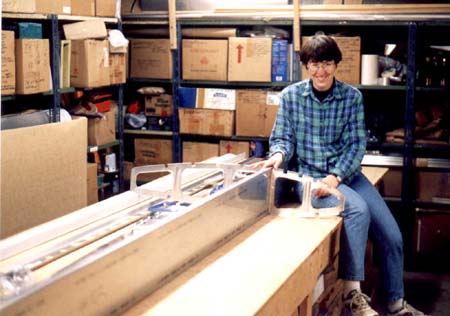
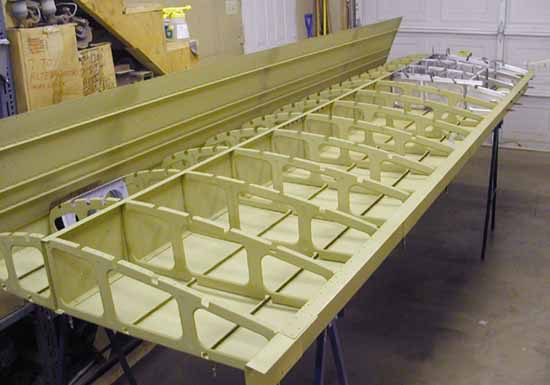
Initial layout of right wing components.
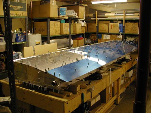
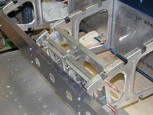
It is helpful to support the spar on 2 x 4s as shown when aligning the ribs
to the spar for drilling rather than aligning one side of the ribs to the spar on the
table top as described in the manual. Clamp 1/8" strips of metal to the spar flanges
on either side of the ribs to simulate the skins and correctly centre them before
drilling.
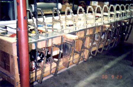
The wing structure continues to take shape, this photo shows the front ribs and skin
stringers.
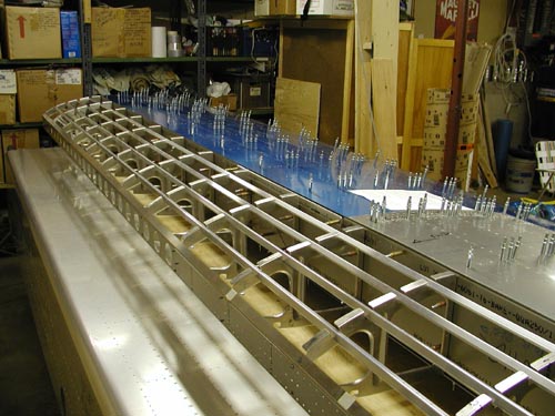
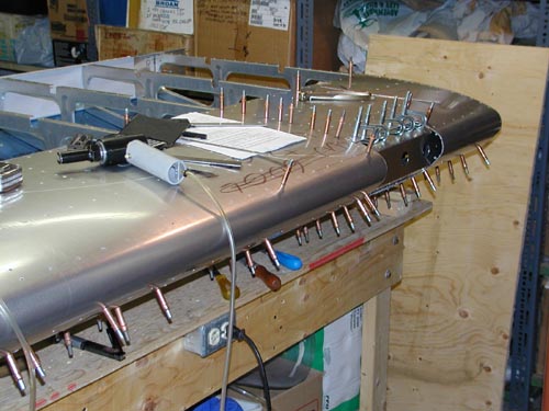
Wing structure with the upper skin and upper tank skin in place.
Landing Light Mount
The optional landing/taxi light mount partially fitted, the front spar will be cut away later. Note the wooden spar positioning fixture in the background.
Progress continues with the landing light mount installation. The leading edge skin has
been mounted, the opening cut and the cover lens supports are being fabricated.
Another view of the landing light mounting, the side lens support is temporarily clamped
in place and the drilling pattern is being transferred via a layout on the paper strip.
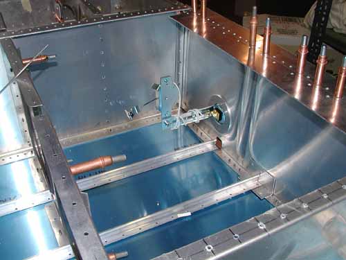
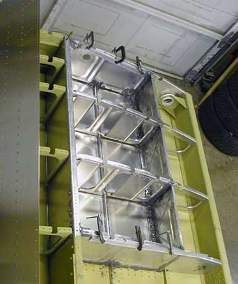
Fuel Tank Baffles
The fuel tank baffles have been fabricated and clecoed in place. Note the fuel tank
bulkheads mounted at left.
Fuel Gauge
We have chosen to install a float type fuel gauge sender rather than the sight gauge
provided with the Murphy kit. The sender installs via a hole in the root rib and is
sealed by a compression gasket.
The clecos shown here will be replaced by threaded fasteners.
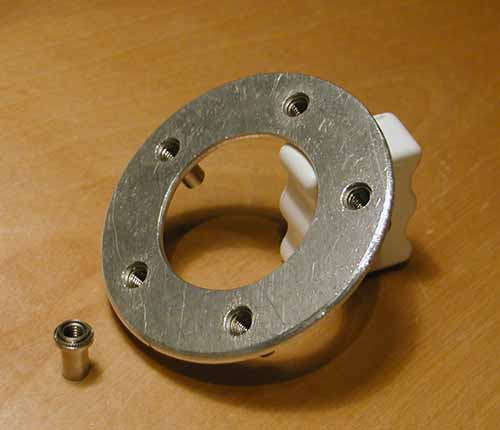
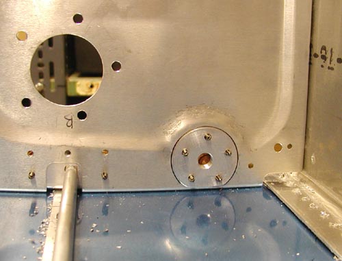
The fuel gauge mount ring is .100" 6061-T6 with PEM type press-in threaded inserts.
The inserts are "blind" so fuel leakage through them is not a concern. The ring will
be bonded in place using the normal AMS-S-8802 fuel tank sealant (commonly known by
the Proseal brand name).
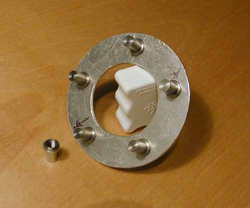
Rear view of the ring and the threaded insert. The insert is PEM P/NBS-032-2.
Fuel Tank Outlets
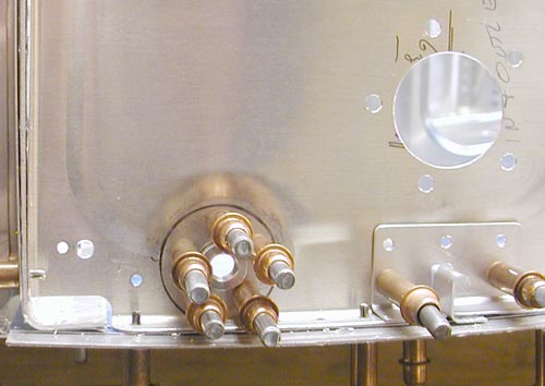
The manual tells you to flatten the embossing of the root rib where the outlets will mount,
however doing that leaves the ribs oil-canning in those areas. If you place a round object
(with radiused edges) under (outside) of the rib, clamp a similar sized disc on top and
carefully tap around it with a hammer, you can raise a nice flat boss on the rib to mount the outlet.
This is the same mounting boss viewed from the inside of the tank area, notice how well the
fitting lays against the newly created boss, this is not difficult to achieve in a short time.
The large hole to the left of the outlet is for the fuel gauge sender.
Wiring Loom
A "conduit" tube is required to house the wires leading to the landing lights and the wing
tip strobes, an automotive wiring loom tube serves well for this purpose. This view is from
the tip end of the wing.
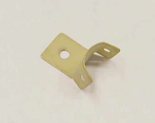
Brackets to support the loom tube were fabricated.
The brackets were mounted to the leading edge ribs using a pre-existing tooling hole.
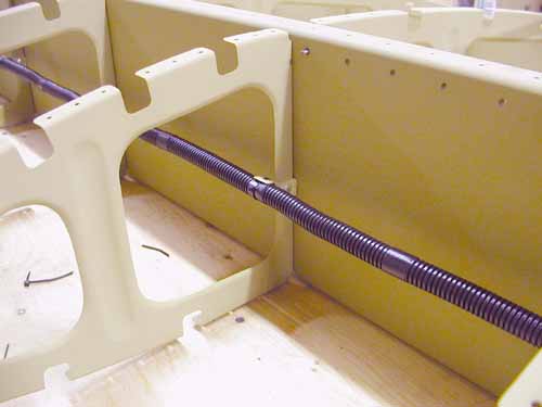
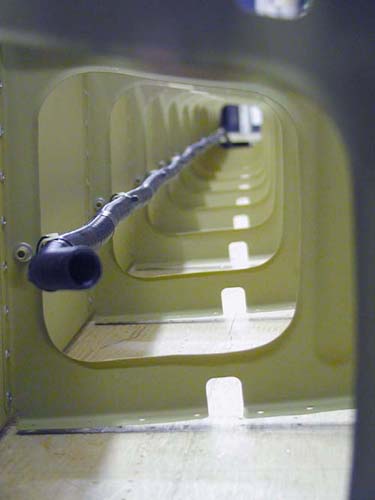
This view shows the loom tube mounted & secured with cable ties.
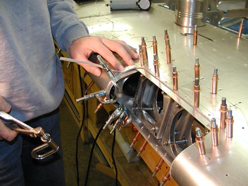
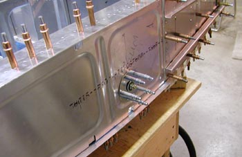
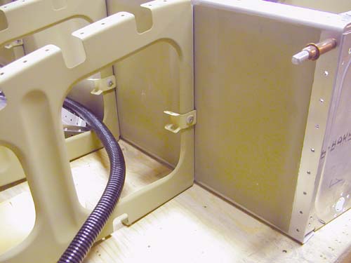
Access Cover/Pitot Mount Ring
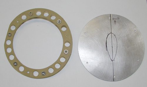
The pitot is mounted to the foreward access cover for the wing strut attach
fasteners. This ring in attached to the inside of the wing skin with countersunk
Avex rivets and carries PEM brand threaded inserts for the screws which hold the
cover/mount plate to the wing skin. The pitot mount will pass through the streamline
shaped hole marked on the plate.
Wet Tank Sealing
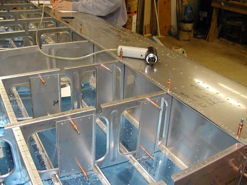
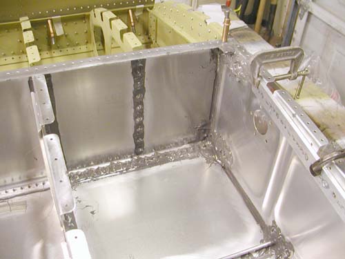
This view shows the completed wet tank area of the left wing.
The C-clamps are holding bar stock along the end ribs to keep them from buckiling
while the sealant cures.
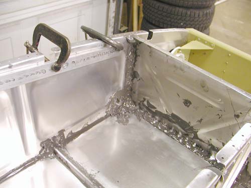
Detail view showing inside front corner of the tank. You can imagine that it is a
rather messy business, it is best done with old coveralls and rubber gloves!
You won't see any photos from the actual sealing sessions, the doors are locked
and anything like cameras you don't want covered in sealant is kept a long way away!
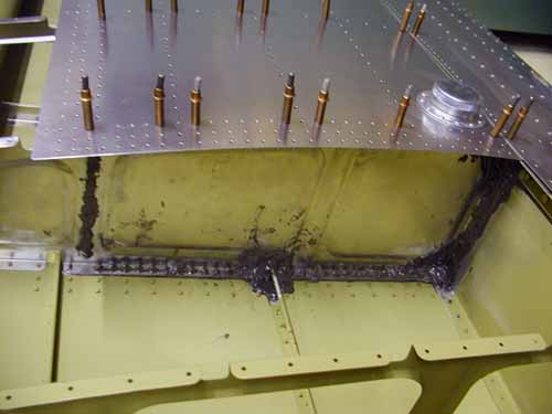
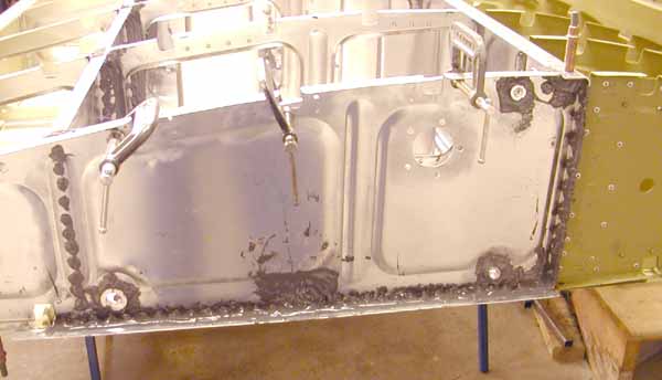
This view shows the inside rear corner of the fuel tank at the fuel outlet, note the
filet of the sealer built up in the upper corner. This will be trimmed before the top
skin is installed.
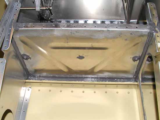
Another detail view, this one showing the outside of one of the bulkheads that form
the back wall of the tank. In the upper left corner of the photo it is important to
get a good portion of sealant between the top edge of the bulkhead and the rib and
get a good filet in the corner and up over onto the top for when the top skin is
mounted later. The excess is cut off before mounting the top skin.
In this view we see the outer tank rib with the top skin clecoed in place.
We started with the fuel caps supplied with the kit but decided to switch to
flush caps after installing the one here. It was fairly easy to do the switch.
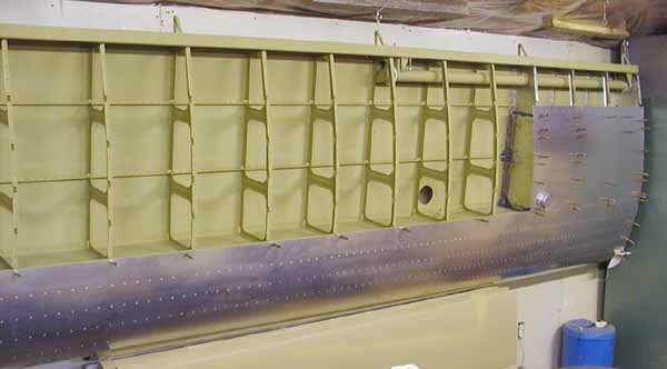
The inboard tank rib, as you can see making a neat job is not easy! The
holes in the upper right are for mounting the fuel level sender.
The finished wing. We stop here until all the components which will
have closed sections are done as far as they can be without closing them.
This is according to Canadian regulations which require a pre-closing inspection.
The left wing, hung up in the storage area. The right wing is also complete and stored.
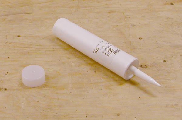
Applying the tank sealing compound can be messy but using these caulking tubes makes the
job much neater, they can be had from C.R. Laurence
at a very inexpensive price. The P/N is 103FLC.